How to Size Off-Grid Solar Power for CCTV Cameras
Learn how to size an off-grid solar power system for CCTV cameras using daily energy use, UK solar conditions, battery autonomy and losses.
By Maxsol Team

An off grid solar power system for CCTV cameras must be sized around the site’s daily energy consumption, not simply the camera count. Add the real power draw of every camera, network device and accessory; convert this into watt-hours per day; then allow for winter solar resource, charging losses and the number of cloudy days the system must bridge.
For a reliable UK installation, start with the poorest expected solar period rather than a summer-only estimate. A system that appears generous on a bright July day may not sustain an always-on CCTV load through shorter, cloudier winter days or when a panel is shaded.
Inventory the full site load
List every device supplied by the solar system, its operating voltage, average watts and hours used per day. CCTV systems are commonly 24-hour loads, so even a modest continuous draw becomes significant over a full day.
Include more than the cameras:
- CCTV cameras, including fixed, turret, bullet and PTZ models
- Infrared illumination, whether built into a camera or fitted separately
- PoE switches, PoE injectors or extenders
- Wireless bridges, access points, 4G/5G routers or cellular gateways
- Network video recorders, edge recorders or local storage devices, where installed at the remote site
- DC-to-DC converters, voltage regulators and passive PoE adaptors
- Cabinet cooling, heaters, door sensors, lighting or telemetry equipment
- Future devices, such as an additional camera or a second wireless link
Use the manufacturer’s stated typical and maximum consumption figures where possible, then validate the figures with a power meter or DC energy monitor on a representative installation. Nameplate wattage is useful for a conservative first design, but it may not reflect normal consumption.
Pay particular attention to night-time demand
Camera power often rises after dark. Infrared LEDs can switch on, PTZ cameras may move more frequently after motion events, and a heater may operate in cold weather. These are precisely the periods when the solar panel is not producing power.
For this reason, record both:
- Average 24-hour power draw for energy sizing.
- Peak simultaneous load for output-port, cable and protection sizing.
A battery with enough watt-hours is not automatically suitable if the system’s DC outputs cannot supply the required voltage, connector type or peak current.
Convert load into daily energy
Calculate the energy used by each device with this formula:
Daily energy (Wh) = device power (W) × operating time (hours per day)
Add every item to find the site’s daily energy requirement.
| Device example | Average power | Daily operating time | Daily energy |
|---|---|---|---|
| Two fixed CCTV cameras | 7 W each | 24 hours | 336 Wh |
| PoE switch | 8 W | 24 hours | 192 Wh |
| Wireless bridge | 5 W | 24 hours | 120 Wh |
| Total site load | 27 W average | — | 648 Wh/day |
In this example, the CCTV site needs 648 Wh per day before system losses. It is not appropriate to compare that figure directly with a battery’s nominal watt-hour rating and assume the battery will run the site for the same number of days.
Add a realistic design margin
The power demand you calculate is a baseline, not a final system requirement. Add margin for:
- Switching and conversion losses
- Battery charging and discharge losses
- Cable voltage drop, especially on long low-voltage runs
- Seasonal changes in camera IR use
- Battery performance in cold conditions
- Equipment ageing and soiling on the solar panel
- An additional camera, radio or network device later
A practical planning approach is to divide the measured load by an assumed system-efficiency factor. For early-stage designs, an allowance in the region of 70% to 80% overall efficiency can provide a more cautious estimate, but the correct figure depends on the equipment architecture and should be checked against the actual controller, conversion and distribution arrangement.
Using 75% as an illustration:
Adjusted daily energy = 648 Wh ÷ 0.75 = 864 Wh/day
This does not mean every system loses exactly 25%; it simply prevents a first-pass calculation from treating panel output and nominal battery capacity as fully usable energy.
Account for solar resource and losses
The solar panel must produce enough energy to replace what the CCTV site uses while there is usable daylight. In the UK, solar generation varies widely by month, site orientation, weather and shade. The design challenge is normally winter, not summer.
A useful sizing formula is:
Required panel power (W) = adjusted daily energy (Wh) ÷ peak sun hours (h)
“Peak sun hours” is a planning value representing the day’s solar energy as an equivalent number of hours at full panel output. Do not substitute daylight hours for peak sun hours: a winter day may be long enough for daytime activity but still deliver limited usable solar energy.
Start with the worst relevant period
For a camera system that must operate year-round, assess the least favourable expected month for the actual location and mounting arrangement. A south-facing, unshaded panel at a suitable tilt will perform very differently from a panel partly shaded by trees, buildings, fencing or a mast.
Check these site conditions before selecting panel wattage:
- Orientation: A broadly south-facing panel usually captures more annual energy in the UK than an east- or west-facing installation.
- Tilt angle: Select an angle appropriate to the mounting location and intended seasonal performance.
- Shade: Even partial shade from a branch, parapet, pole or nearby building can materially reduce production.
- Soiling: Dust, bird droppings, leaves and snow reduce light reaching the panel.
- Mounting security: The panel must remain correctly aimed and withstand local wind exposure.
- Cable route: Keep DC cable runs sensible and calculate voltage drop rather than assuming it is negligible.
- Temperature: Cold weather can affect batteries and may change the site’s electrical demand.
If the calculation shows that the panel cannot realistically replace the load during the poorest solar period, increasing battery capacity alone will not solve the issue indefinitely. The battery will eventually discharge unless the site has enough solar harvest, a reduced load, seasonal operating changes or another charging source.
Separate energy balance from battery backup
Two separate questions must be answered:
- Can the panel generate enough average energy to replenish the battery?
- Can the battery carry the load through nights and poor-solar days?
A good answer to one does not guarantee the other. A large panel with a very small battery may lose power overnight; a large battery with an undersized panel may survive briefly but fail after several dull days.
Choose battery autonomy
Battery autonomy is the number of days, or part-days, that the system should continue to run with little or no solar input. For an always-on remote CCTV site, decide the autonomy target before choosing a kit.
Use this starting calculation:
Required nominal battery energy (Wh) = adjusted daily energy (Wh/day) × required autonomy (days) ÷ permitted usable battery fraction
The permitted usable fraction is a design allowance. Avoid assuming that all nominal battery energy can be repeatedly taken from a battery under every temperature and load condition. The appropriate allowance depends on the battery management system, low-voltage cut-off behaviour, target battery life and the product documentation.
For the earlier 648 Wh/day example, adjusted to 864 Wh/day:
- One day of autonomy needs at least 864 Wh of usable stored energy.
- Two days of autonomy needs at least 1,728 Wh of usable stored energy.
- A nominal capacity calculation must then account for the permitted usable portion of the battery.
This immediately shows why a system should not be chosen on panel wattage or camera count alone.
Match autonomy to site risk
The right autonomy target depends on the consequence of downtime and whether the site can be reached easily.
A low-risk, accessible site may accept shorter backup if it has good solar exposure and can be serviced promptly. A remote location, critical perimeter or unmanned compound generally calls for a more conservative energy assessment, especially where winter access is difficult.
Consider:
- How many consecutive poor-solar days are plausible at the location
- Whether the cameras are evidence-critical or mainly for general observation
- Whether an outage causes operational, safety or security issues
- How quickly an installer can attend the site
- Whether the system can send low-battery alerts
- Whether an auxiliary charging option is available
Do not overlook temperature. Battery charging and discharge behaviour can be affected by low temperatures, so confirm the specified operating and charging conditions for the selected equipment and the planned enclosure arrangement.
Compare 192Wh to 1280Wh CCTV solar kit examples
The following Maxsol systems provide documented panel and battery capacity examples for comparison. They are not a promise of runtime for a particular CCTV configuration, location or season. Actual results depend on load, solar input, losses, mounting, battery settings and environmental conditions.
| System example | Documented panel | Documented battery | Initial comparison use |
|---|---|---|---|
| CS3015 | 30 W monocrystalline panel | 12.8 V 15 Ah, 192 Wh LiFePO4 | Small, measured DC load with modest energy demand |
| CS6030 | 60 W panel | 12.8 V 30 Ah, 384 Wh LiFePO4 | Higher daily energy requirement or more storage than a 192 Wh option |
| CS12060 | 120 W panel | 12.8 V 60 Ah, 768 Wh LiFePO4 | Sites needing materially greater generation and stored energy |
| CS200100 | 200 W system configuration | 12.8 V 100 Ah, 1280 Wh battery | Larger calculated load or higher autonomy requirement |
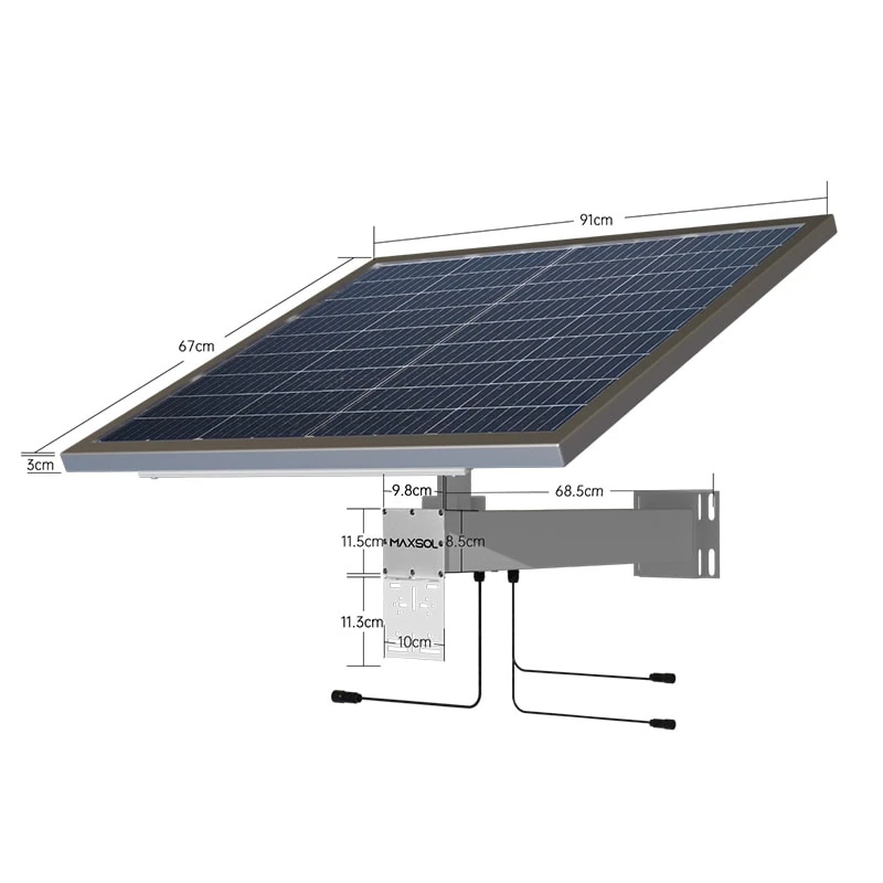
The CS3015 30W, 15Ah, 192Wh solar system combines a 30 W monocrystalline panel, 12.8 V 15 Ah 192 Wh LiFePO4 battery, MPPT controller and three DC12V output ports. Its 192 Wh battery figure is nominal stored energy, not an assumed 192 Wh of delivered CCTV runtime.
The CS6030 60W, 30Ah, 384Wh solar system doubles the documented battery capacity to 384 Wh and uses a 60 W panel. It may be a comparison point where calculations exceed a smaller system’s energy allowance, but the voltage, connector and current requirements of cameras and network equipment must still be verified.
The CS12060 120W, 60Ah, 768Wh solar system provides a documented 120 W panel and 768 Wh battery capacity. It is an option to assess for systems with a larger continuous load, a higher resilience target or a location where seasonal solar yield requires a more substantial panel.
The CS200100 200W, 100Ah, 1280Wh solar system documents a 200 W configuration with a 12.8 V 100 Ah 1280 Wh battery. A system at this capacity should still be checked against the site’s calculated daily energy balance, not selected simply because it has the largest nominal battery in this comparison.
A quick capacity sense-check
Before considering solar recharge, divide nominal battery capacity by the continuous load only as a rough screening exercise:
Indicative hours = nominal battery Wh ÷ average site watts
For example, a 384 Wh battery serving a constant 16 W load gives:
384 Wh ÷ 16 W = 24 hours nominal
That is not a runtime guarantee. It excludes usable-capacity limits, conversion losses, temperature, peak loads, battery condition and solar contribution. It is useful only for identifying an obvious mismatch, such as pairing a small battery with a large round-the-clock load.
Validate before purchase
A robust off-grid CCTV design is verified at electrical, environmental and operational level. Work through the following checks before specifying equipment.
Confirm the DC and PoE architecture
Document the path from battery to every load:
- Is each device powered directly at 12 V DC, through a DC converter or by PoE?
- What voltage range does each camera and radio accept?
- What is the maximum and typical power draw of each PoE device?
- Does the PoE switch or injector require a particular input voltage?
- Are passive PoE and IEEE PoE devices being kept separate and correctly matched?
- Is a DC-to-DC converter required to maintain the proper voltage?
- Can each output and connector supply the needed current safely?
Do not assume that a DC12V output can directly power every camera, PoE switch or radio. Check voltage, polarity, plug dimensions, current capacity and any conversion requirement.
Check maximum demand, not just average watts
The battery and distribution arrangement must cope with peak demand. This can occur when multiple cameras enter night mode, a PTZ camera moves, a radio transmits, storage writes data or a device starts up.
Calculate:
Peak power = sum of the highest simultaneous device loads
Then convert it to current at the relevant DC voltage:
Current (A) = power (W) ÷ voltage (V)
Use this figure when reviewing output-port limits, cable sizing, fuses, connectors and converters. A system can have adequate daily energy but still suffer voltage drop or protective shut-down during a peak event.
Plan for protection and maintainability
An outdoor power system needs more than a panel and battery. The final design may require appropriately specified fusing, isolation, surge protection, cable glands, weatherproof enclosures, strain relief and earthing arrangements appropriate to the equipment and site.
Also establish a maintenance plan:
- Inspect panel cleanliness and new sources of shade.
- Check cable condition, glands and mounting security.
- Review battery voltage and low-battery events where monitoring is available.
- Confirm that added cameras have not exceeded the original energy budget.
- Recalculate after changing camera settings, IR behaviour or recording equipment.
Avoid common sizing mistakes
The most frequent errors are straightforward but costly:
- Sizing by camera count. Two cameras can use very different amounts of energy depending on PoE class, IR, heaters and network equipment.
- Using only nominal battery Wh. Usable energy is lower once operating limits and losses are considered.
- Designing around summer sunlight. Winter solar resource and shade determine year-round resilience.
- Ignoring the router or wireless bridge. Communications equipment can be a substantial 24-hour load.
- Forgetting night mode. IR lighting changes the load when generation is zero.
- Adding equipment later without recalculation. One extra camera may materially reduce autonomy.
- Assuming all 12 V equipment is directly compatible. Voltage range, plugs, current and PoE method all matter.
- Treating a larger battery as a cure for inadequate solar input. Stored energy will be depleted if the panel cannot replenish it.
Frequently asked questions
How many CCTV cameras can an off-grid solar system run?
There is no reliable fixed camera number. Calculate the combined daily watt-hours for cameras, PoE equipment, networking, recording and accessories. A low-power fixed camera and a PTZ camera with active infrared illumination can have very different energy demands.
Is a 192Wh battery enough for a CCTV camera?
It may be enough for a small, measured load for a limited period, but it cannot be confirmed from battery capacity alone. Divide nominal capacity by average watts only as an initial screen, then allow for losses, usable capacity, night-time demand and solar recharge.
What panel size is needed for solar CCTV in the UK?
The required panel size depends on daily energy use and the lowest expected solar resource at the installation site. Calculate panel power from adjusted daily energy divided by suitable peak sun hours, then assess orientation, tilt, shade and winter operation.
Should I size for one or two days of battery autonomy?
Choose autonomy based on the impact of downtime, site access and expected poor-solar periods. One day may suit some accessible, low-risk sites; remote or important surveillance locations often require a more conservative design. The panel must also be capable of restoring the battery after poor weather.
Use the calculations above to compare the linked Maxsol models against your port count, load profile, cable distance, required voltage, local environment and any monitoring or management requirements.