How to Reduce Remote CCTV Installation Costs
Compare grid, solar and wireless options for remote CCTV, then use a lifecycle cost worksheet to control trenching, maintenance and repeat visits.
By Maxsol Team

To reduce remote CCTV installation costs, avoid choosing power and data methods in isolation. Define the required camera coverage, load, recording path and service life first, then compare grid-fed PoE, off-grid solar and hybrid designs on exactly the same basis.
The lowest initial quotation is not necessarily the cheapest solution. Trenching, grid extension, access equipment, commissioning, mobile data subscriptions, battery replacements and repeat visits can materially change the lifecycle cost. Solar and wireless links can remove civil works, but only where the energy budget, line of sight and maintenance arrangements support them.
Establish a like-for-like scope and cost baseline
A meaningful comparison begins with a fixed technical scope. If one design includes resilient backhaul, winter autonomy and replacement batteries while another omits them, their totals are not comparable.
Record the following requirements before requesting prices:
- Number, type and location of cameras
- Maximum and typical power demand per camera
- Night-time loads such as infrared illumination
- Required recording location and retention arrangement
- Continuous or scheduled operation
- Distance from the nearest usable mains supply
- Distance to the network or recording point
- Existing ducts, poles, cables and structures that may be reused
- Required network bandwidth and latency
- Environmental exposure and enclosure requirements
- Site access restrictions and working-hour limitations
- Expected project life
- Required resilience during mains, backhaul or equipment failure
- Responsibility for maintenance, subscriptions and replacements
Treat PoE correctly in this baseline: Power over Ethernet is a distribution method, not an energy source. A PoE switch or injector still needs energy from the grid, a solar-battery system or another suitable supply.
Build the load schedule first
List every continuously powered device, not just the cameras. Depending on the architecture, the remote load may include:
- Cameras
- PoE switches or injectors
- Wireless radios
- Media converters
- Routers or mobile gateways
- Heaters, fans or enclosure controls
- Monitoring and protection equipment
- Conversion losses and standby loads
Use maximum specified consumption for cable, converter and protection sizing. For solar-energy planning, also model a credible operating profile rather than assuming that every device always consumes either its idle or maximum figure.
Separate essential and optional costs
Some proposed features may be valuable without being essential to the surveillance objective. Separate them so procurement teams can see where money is being spent.
For example, compare:
- The minimum compliant design
- The preferred operational design
- The resilient design with additional autonomy or backhaul
This prevents an enhanced solar proposal from being unfairly compared with a basic grid installation.
Compare grid extension and solar power
Grid-fed PoE is often straightforward when a compliant electrical supply already exists near the camera position. It becomes less attractive when the project requires long trenches, road or hard-surface reinstatement, new metering, extensive containment or third-party connection work.
An off-grid solar system can avoid some of those costs, but it introduces a different engineering task. The designer must account for the full DC load, local solar conditions, panel orientation, shading, seasonal variation, battery charging limits and required autonomy. A nominal battery capacity alone does not establish runtime.
A hybrid approach may be appropriate where different parts of the site face different constraints. Examples include a grid-powered recording point with solar-powered remote cameras, or an existing powered building connected to remote poles by wireless backhaul.
| Decision factor | Grid-fed PoE | Off-grid solar with PoE distribution | Feasible hybrid approach |
|---|---|---|---|
| Best fit | Reliable power already exists nearby | Grid extension is difficult and the site has suitable solar exposure | Power is available at some locations but not all |
| Main installation costs | Electrical work, containment, trenching and reinstatement | Panel, battery, controller, mounting, protection and commissioning | Combination of local power, solar hardware and backhaul |
| Civil works | May be substantial over long distances | Can be reduced if equipment is pole- or structure-mounted | Usually concentrated around selected powered points |
| Seasonal design requirement | Usually limited to supply resilience | Essential for panel and battery sizing | Required for solar-powered sections |
| Routine operating cost | Electricity and any site supply charges | Inspection, cleaning where necessary and battery replacement | Electricity plus solar-system maintenance |
| Main technical risks | Connection delay, voltage drop, cable damage and disruption | Shading, poor energy budget, charging restrictions and battery degradation | More interfaces and a less uniform maintenance model |
| Expansion | Often simple within available power and network capacity | Additional load may require larger power hardware | Depends on spare capacity at each powered or solar node |
Assess solar power using delivered energy, not labels
The Maxsol CS12060 solar power system is one selection example. Its documented configuration includes a 120W monocrystalline panel, a 12.8V 60Ah 768Wh LiFePO4 battery, an MPPT controller and three DC12V outputs; RS485 is optional.
Those figures are inputs to a design assessment, not a guarantee of CCTV autonomy. Nominal battery watt-hours are not the same as usable energy delivered to cameras and network equipment. Conversion losses, controller limits, battery protection, charging temperature, cable losses, environmental conditions and the permitted depth of discharge must all be considered.
Before specifying any solar system, confirm the current datasheet and supplied configuration for:
- Controller PV voltage, current and power limits
- Battery charging-temperature limits
- Low-voltage and over-current protection
- Output voltage and connector arrangement
- Mounting and environmental protection
- Monitoring interfaces, if required
- Compatibility with the selected PoE conversion hardware
Do not assume that a DC12V output can be connected directly to an IEEE PoE device. The correct injector, switch or DC-DC converter must provide the voltage, power negotiation and pin arrangement required by the endpoint.
A hypothetical load check
Consider a purely hypothetical remote point with the following assumed loads:
- Two cameras at 8W each
- One radio at 6.5W
- Conversion and supporting equipment at 4W
The assumed continuous load would be 26.5W, or 636Wh over 24 hours before additional design margins. This is a worksheet example only; the camera and conversion figures are assumptions, not measured product performance.
Although a battery may carry a nominal 768Wh label, subtracting 636Wh from that figure is not a valid autonomy assessment. The design must use allowable delivered energy and include losses, operating limits, ageing allowances and the energy required to recover after low-generation periods. There is no universal runtime or 24/7 guarantee based on nominal watt-hours.
Evaluate wireless backhaul against new cabling
Wireless backhaul can reduce trenching and reinstatement costs when clear line of sight is available between suitable mounting points. It should not be selected simply because the distance label on a product appears sufficient.
A wireless survey needs to assess:
- Clear line of sight and Fresnel-zone clearance
- Mounting height and pole stability
- Trees, vehicles, buildings and future obstructions
- Local interference and channel availability
- Required application throughput in both directions
- Camera bit rates and traffic peaks
- Weather exposure and cable entry
- Earthing, surge protection and power arrangements
- Local radio rules
- Alignment access during installation and maintenance
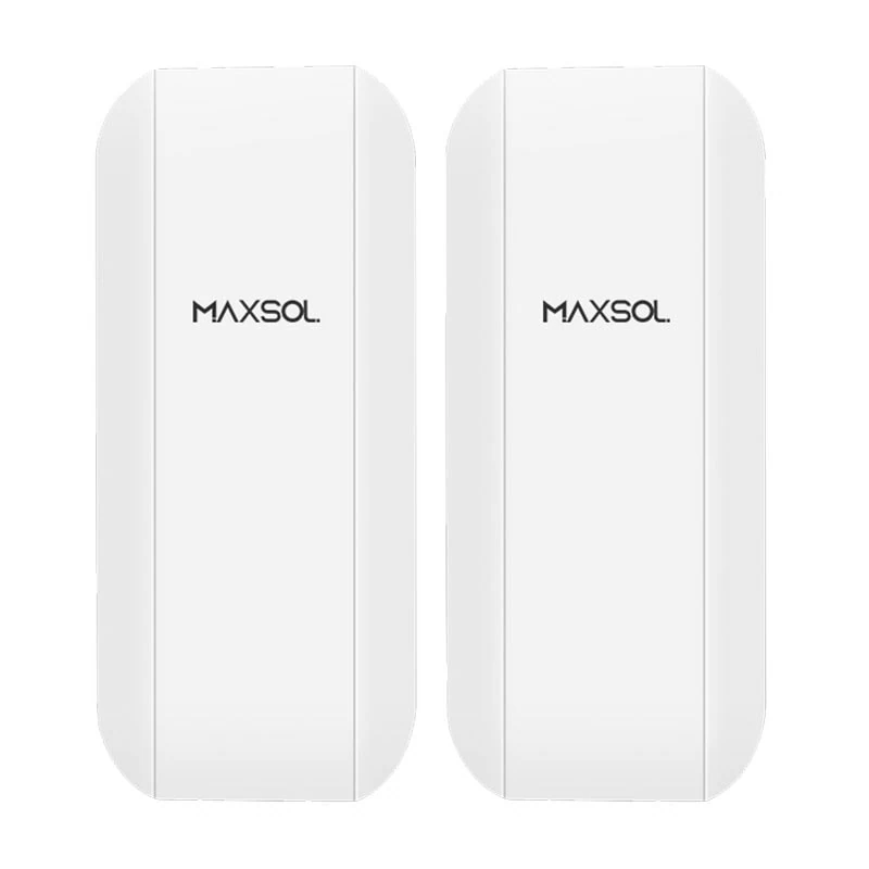
The Maxsol CPE295 5.8GHz wireless CPE documents 5.8GHz operation, a 2×2 14dBi directional MIMO antenna, one Gigabit LAN port, IEEE 802.3af/at or 9–48V DC power support, and 6.5W full-load consumption. Range and wireless-rate labels do not guarantee site distance or application throughput. Verify line of sight, interference, local radio requirements and the current product configuration.
The CPE295 and CS12060 are selection examples, not a tested compatible bundle. Account for the radio’s input requirements, PoE conversion, all other loads and controller limits before combining equipment.
Compare wireless, copper and fibre on the same basis
Wireless is not always the cheapest option. Existing ducts may make fibre economical, while a short compliant cable route may be simpler to maintain than a radio link.
Include the following for each transport method:
| Cost item | New copper route | Fibre route | Wireless backhaul |
|---|---|---|---|
| Cable or radio hardware | Cable, termination and network ports | Fibre, optics, termination and enclosures | Radios, brackets and network interfaces |
| Route preparation | Duct, containment or trenching | Duct, containment or trenching | Survey and mounting positions |
| Protection | Surge, earthing and weatherproof entry | Mechanical protection and suitable enclosures | Surge, earthing and weatherproof entry |
| Commissioning | Cable certification and PoE checks | Optical tests and link checks | Alignment, interference checks and throughput tests |
| Ongoing work | Repair after cable damage | Specialist repair where required | Realignment, firmware management and interference diagnosis |
For powered copper links beyond a conventional channel, review the available architectures in the guide to extending PoE for IP cameras over long distances. Where electrical isolation, bandwidth or long cable routes favour optical transport, use the SFP uplink guide for CCTV fibre networks to identify the relevant switch ports, optics and fibre checks.
Reusing existing infrastructure can reduce cost, but only after inspection and testing. An undocumented cable, corroded enclosure or blocked duct can create more labour than a planned replacement.
Reduce repeat visits through surveys and bench checks
One failed installation visit can erase a large portion of the savings achieved by choosing cheaper hardware. Surveys and bench checks are therefore cost controls, not administrative extras.
Complete a site survey
A practical pre-installation survey should confirm:
- Exact mounting positions and camera views
- Safe access methods and working space
- Cable distances and routes
- Pole condition and loading constraints
- Solar orientation and shading throughout the relevant periods
- Wireless line of sight from the intended mounting height
- Availability and condition of existing mains supplies
- Enclosure, ventilation and condensation requirements
- Earthing and surge-protection arrangements
- Network addressing and recording destinations
- Who can authorise access, shutdowns and changes
Photographs, annotated plans and measured distances help installers arrive with the correct brackets, glands, cable lengths and access equipment.
Bench-test the complete chain
Assemble as much of the system as practical before sending it to site. A useful bench process includes:
- Confirm device input voltages and PoE requirements.
- Load the intended firmware and configuration.
- Assign addresses and record credentials securely.
- Connect the camera, switch, injector, converter and radio chain.
- Check video under representative settings.
- Confirm the recorder receives and retains the stream.
- Measure actual DC load in relevant operating states.
- Simulate restart and power recovery.
- Label cables, ports, equipment and configuration files.
- Create a commissioning sheet for the site team.
Bench measurements can improve an energy model, but they do not replace design margins or environmental assessment. A camera may draw more power at night, during heater operation or when infrared lighting is active.
Define acceptance tests before installation
Agree what constitutes completion. Tests may include:
- Camera view and focus
- Recorded image retrieval
- Link stability and negotiated speed
- Wireless application throughput
- PoE voltage and power behaviour
- Solar charging status
- Battery protection and recovery behaviour
- Remote management access
- Alarm or fault reporting
- Photographic records and updated diagrams
Clear acceptance criteria reduce disputes and prevent unnecessary return visits to investigate behaviour that was never defined.
Include maintenance, replacements and operating costs
Lifecycle costing should cover the intended evaluation period and use consistent treatment of VAT. Compare every option either excluding VAT or including VAT; do not mix the two.
Use supplier quotations and internal labour rates rather than assumed market averages. No universal percentage saving or payback period applies across remote CCTV projects.
A transparent worksheet can use the following structure:
| Cost category | Quantity | Unit cost | Initial cost | Recurrence or replacement year | Lifecycle total |
|---|---|---|---|---|---|
| Site survey and design | |||||
| Grid connection or extension | |||||
| Trenching, ducting and reinstatement | |||||
| Poles, brackets and foundations | |||||
| Solar panel, battery and controller | |||||
| PoE switches, injectors and converters | |||||
| Copper, fibre or wireless backhaul | |||||
| Enclosures, protection and earthing | |||||
| Installation labour and access equipment | |||||
| Configuration and commissioning | |||||
| Electricity or communications subscriptions | |||||
| Planned inspections and cleaning | |||||
| Battery and equipment replacements | |||||
| Expected fault-response visits | |||||
| Removal or end-of-project work |
For each option, calculate:
Lifecycle cost = initial project cost + recurring operating costs + planned replacements + expected maintenance costs
Document every assumption beside the worksheet, including the evaluation period, labour rate, access cost, subscription term and replacement basis. If the timing of expenditure matters to procurement, apply the organisation’s approved discounting method rather than inventing one for the comparison.
Allow for different failure and maintenance modes. Grid systems may incur cable-damage or supply-related call-outs. Solar sites require battery, panel, mounting and charging-system inspections. Wireless links may require alignment or interference investigation. Fibre can reduce electrical-path risks but may need specialist termination or repair resources.
Choose the lowest viable lifecycle cost
The correct objective is not the lowest hardware cost. It is the lowest lifecycle cost among designs that satisfy the operational requirement.
Use this sequence:
- Reject technically unsuitable options. Eliminate solar where generation, mounting or maintenance conditions are inadequate. Eliminate wireless where line of sight or application throughput cannot be supported.
- Reuse infrastructure selectively. Retain cables, ducts, poles and supplies only after inspection and testing.
- Minimise civil works. Compare rerouting, wireless and local solar before approving expensive trenching or grid extension.
- Keep the architecture simple. Every converter, connector and power stage adds installation and diagnostic work.
- Price complete systems. Include protection, mounting, commissioning, subscriptions and replacements.
- Test before deployment. Verify device interoperability, actual loads and configuration on the bench.
- Document maintenance access. A low-cost location can become expensive if every inspection requires specialist access equipment.
- Compare on a common project life. Apply the same operating period and service assumptions to every option.
A grid-fed design will often remain the sensible choice where power and containment already exist. Solar becomes more competitive when grid extension and civil works dominate, provided the energy model is sound. Wireless backhaul is most valuable where physical cabling is disruptive or impractical and the radio path can be verified. Hybrid designs can control costs by using each method only where it has a clear site-specific advantage.
The practical next step is to complete the load, distance and lifecycle worksheet, then compare the linked Maxsol selection examples with the required port count, power load, link distance, environmental conditions and management functions. Confirm current datasheets and supplied configurations before deciding whether either model belongs in the final design.