12V vs 24V vs 48V for Outdoor PoE Power
Compare 12V, 24V and 48V outdoor PoE DC power, calculate cable loss, allow for startup sag and specify protected, serviceable circuits.
By Maxsol Team

For most outdoor PoE surveillance systems, 48V distribution is the practical choice for longer cable runs or higher loads because it carries the same power at lower current, reducing cable loss and voltage drop. A 24V system can be a useful compromise where solar controllers, batteries and industrial networking equipment share that voltage range. A 12V system is generally better suited to short, low-power branches or equipment designed specifically around a 12V source.
However, the correct answer to 12V vs 24V vs 48V outdoor PoE DC power depends on operating ranges rather than nominal labels alone. Check the lowest source voltage, startup current, cable resistance, converter limits, PoE method and protection arrangement before selecting the distribution voltage.
| Distribution option | Typical design advantage | Main limitation | Often suitable for |
|---|---|---|---|
| 12V DC | Direct use with many compact batteries and auxiliary devices | Highest current and cable loss for a given power | Short, low-power branches |
| 24V DC | Lower current than 12V and common in industrial DC systems | May still require conversion for cameras or PoE equipment | Medium-distance mixed power and networking systems |
| 48V DC | Lowest current of the three for equal power; well suited to longer runs | Requires compatible equipment and careful voltage/protocol checks | Higher-power or distributed outdoor PoE networks |
These are selection tendencies, not universal compatibility rules. A device marked “48V” is not automatically compatible with every 48V source or PoE implementation.
Map sources, loads and voltage ranges
Begin with a power-path drawing rather than a list of nominal voltages. It should show every conversion and connection from the energy source to the final powered device:
- Solar panel or mains-derived DC source
- Charge controller
- Battery and battery protection
- Main fuse or circuit protection
- DC distribution branches
- DC-to-DC or DC-to-PoE converters
- PoE switch or injector
- Ethernet cable
- Camera, radio, access point or other powered device
For each block, record its full input and output voltage range, continuous current, startup or surge requirement, polarity and environmental limits. Nominal voltage is only a category. Battery terminal voltage changes with state of charge, charging conditions, temperature, current and protective cut-offs.
The critical compatibility test is:
- The source must remain above the load or converter’s minimum input voltage during normal operation and startup.
- The source must remain below the maximum input voltage during charging or other high-voltage conditions.
- The converter output must match the powered device’s voltage, polarity, pinout and PoE protocol.
- Every intermediate connector, fuse, switch and cable must carry the expected current.
For example, the Maxsol CS12060 120W solar power system documents a 120W monocrystalline panel, a 12.8V 60Ah 768Wh LiFePO4 battery, an MPPT controller and three DC12V outputs. RS485 is optional. Those nominal figures do not establish usable delivered energy, autonomy or compatibility with a particular PoE load. Confirm the current product data for controller PV limits, charging limits, battery charging temperatures and protection behaviour.
Battery chemistry affects charging, storage and protection decisions, but it should not replace a complete DC power-path assessment. For a focused overview, see the guide to LiFePO4 battery benefits and limitations for solar CCTV.
Distinguish DC voltage from PoE compatibility
Do not treat “48V DC” and “48V PoE” as interchangeable descriptions. The powered device may expect IEEE detection and power negotiation, or it may use a passive arrangement with fixed voltage and pin allocation.
Before connection, verify:
- Active IEEE or passive PoE operation
- Required voltage at the powered-device input
- Polarity and pair allocation
- Maximum and minimum operating voltage
- Startup demand
- Power class or negotiated power, where applicable
- Whether the injector, switch and device support the same Ethernet data rate
Applying voltage to an incompatible pinout can damage equipment even when the nominal voltage appears correct.
Allow for startup sag and converter limits
A system that works with one camera during a bench test can still reset when all loads start together. Motors, infrared illumination, heaters, wireless transmitters, processors and input capacitors can produce short demand peaks above the steady-state reading.
During startup, voltage can fall because of:
- Battery internal resistance
- A controller’s current limit
- Long or undersized cables
- Fuse and connector resistance
- DC-to-DC converter input limits
- Several devices starting simultaneously
- Low battery state of charge
- Temperature-dependent source or battery behaviour
The key design value is the voltage measured at the converter or switch input during the transient, not the open-circuit battery voltage.
Converters also need input power greater than their output power because conversion is not lossless. For preliminary sizing:
Input power = output power ÷ assumed conversion efficiency
Use a conservative project assumption rather than a published maximum-efficiency figure. Efficiency normally varies with input voltage, output voltage, temperature and load.
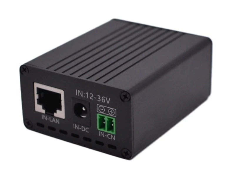
The Maxsol POE24V DC-to-PoE converter accepts 12–36V DC and provides an adjustable 12–57V PoE output, Gigabit Ethernet and an LCD voltage display. Its documented continuous load for 12V-to-48V conversion is no more than 30W. The stated conversion efficiency of up to 94% is a maximum, not a value to use as a guaranteed design assumption.
IEEE powered-device detection or negotiation is not established by those facts. Confirm voltage, polarity, pinout and protocol compatibility before pairing the converter with a camera, radio or access point.
Do not combine nameplate maximums
Avoid building the design by taking every component’s maximum rating at face value. Apply margins for:
- Converter derating at enclosure temperature
- Simultaneous port demand
- Cable and connector losses
- Battery voltage near its low operating limit
- Startup current
- Controller and battery protection thresholds
- Auxiliary loads such as fans, heaters, lighting or monitoring equipment
For multi-port systems, calculate both the total PoE budget and the demand on individual ports. The separate guide to calculating a PoE power budget for security cameras explains how to account for camera operating modes and port-level limits.
Calculate round-trip cable voltage drop
DC voltage drop must include both the outgoing and return conductors. Using one-way cable resistance understates the loss by approximately half in a simple two-conductor circuit.
Use:
Round-trip resistance = resistance of outgoing conductor + resistance of return conductor
Voltage drop = current × round-trip resistance
Cable power loss = current² × round-trip resistance
Remote voltage = source voltage − voltage drop
Cable resistance should reflect the installed length, conductor material, cross-sectional area and expected operating temperature. Add connector and fuse-holder resistance where it is material.
Hypothetical comparison at equal power
The following is an illustrative calculation only, not measured product performance.
Assumptions:
- Load power for the first-pass comparison: 48W
- Total round-trip circuit resistance: 0.20Ω
- Nominal source voltages: 12V, 24V and 48V
- Current approximated as power divided by nominal voltage
- No startup surge or converter loss included
- Source voltage remains fixed for the calculation
| Nominal voltage | Approximate current | Voltage drop | Approximate remote voltage | Cable loss |
|---|---|---|---|---|
| 12V | 4.00A | 0.80V | 11.20V | 3.20W |
| 24V | 2.00A | 0.40V | 23.60V | 0.80W |
| 48V | 1.00A | 0.20V | 47.80V | 0.20W |
Doubling the voltage halves the current for the same power. Because cable loss is proportional to current squared, the reduction can be substantial.
The percentage voltage drop also matters. In this hypothetical example, 0.8V represents a much larger share of a 12V supply than 0.2V does of a 48V supply. This is one reason a low-voltage source can appear healthy at the cabinet while the remote converter repeatedly restarts.
A practical voltage-drop method
For each branch:
- Identify the highest credible continuous load.
- Add relevant converter input power and auxiliary loads.
- Estimate the startup or short-duration peak separately.
- Obtain conductor resistance for the installed length and expected temperature.
- Calculate outgoing plus return resistance.
- Include material connection resistance.
- Calculate remote voltage at both continuous and peak current.
- Compare the result with the load’s minimum input voltage.
- Repeat using the source’s lowest expected operating voltage.
- Confirm the result by measurement after installation.
If the margin is inadequate, consider a larger conductor, shorter route, higher distribution voltage, local conversion or separate branches. Raising a converter’s output setting does not correct excessive loss on its input cable.
Size branch protection and service isolation
Outdoor DC systems need protection arranged around the conductors and branches, not merely around the total battery capacity. A large battery can supply substantial fault current even when the normal load is small.
Provide branch protection near the source of each outgoing circuit. Select it by considering:
- Conductor current-carrying capacity
- Maximum permitted current for connectors and devices
- Normal continuous current
- Startup and inrush current
- Ambient and enclosure temperature
- Fuse or breaker time-current behaviour
- Battery and controller instructions
- The available fault current
- Coordination with downstream protection
A protective device should tolerate legitimate startup demand without nuisance operation, but it must still protect the smallest conductor or component in the branch. Do not increase the fuse rating merely because repeated startup events cause it to open; investigate the inrush, cable sizing and load sequence first.
Useful design provisions include:
- Separate protection for the PoE switch, converters and auxiliary loads
- Clearly labelled polarity
- Finger-safe terminals or guarded battery connections
- A service disconnect that removes power from the equipment being maintained
- Lock-off or other isolation arrangements where the project requires them
- Protection against accidental reverse polarity
- Documented fuse or breaker ratings inside the enclosure
- Spare terminals kept electrically safe rather than left exposed
Whether isolation must disconnect one conductor or all live conductors depends on the source topology, bonding arrangement, equipment instructions and applicable project requirements. Establish this during design rather than making assumptions during installation.
Surge protection also requires a coordinated approach. A protective device on the Ethernet side does not necessarily protect the DC input, solar input or other metallic route. Review all paths entering the outdoor cabinet and keep protective conductors short and direct.
Manage enclosure temperature, moisture and bonding
Electrical ratings stated under controlled conditions may not represent a sealed outdoor cabinet exposed to solar heating. Internal temperatures can exceed the surrounding air temperature, particularly when the panel, battery, converters and switch are installed in a compact enclosure.
Prepare a heat budget covering:
- PoE switch losses
- DC-to-DC conversion losses
- Battery charging heat
- Controller losses
- Auxiliary power supplies
- Solar gain on the enclosure
- Reduced airflow caused by filters or internal cable congestion
Maintain space around heat-producing components and follow their mounting orientation requirements. Where ventilation or cooling is used, consider its power consumption, maintenance needs and effect on moisture ingress.
Moisture management is not limited to choosing an enclosure ingress rating. Poorly positioned cable entries, damaged glands, condensation, blocked drains and pressure changes can all create problems. Use suitable glands, drip loops and cable support, and separate wet-entry areas from sensitive electronics where practical.
Bond exposed conductive parts according to the system’s earthing design and applicable installation requirements. Avoid casual links between DC negative, protective earth, cabinet metal, surge-protection conductors and cable screens. An unintended connection can create circulating current or defeat the intended protection arrangement.
For sites exposed to lightning or significant surge risk, coordinate:
- Cabinet bonding
- Mounting-pole or structure bonding
- DC surge protection
- Ethernet surge protection
- Solar-array cable routing
- Protective conductor routing
- Separation between protected and unprotected wiring
A specialist assessment may be appropriate where the site structure, exposure or existing lightning-protection system makes the bonding arrangement complex.
Test worst-case voltage and recovery
Commissioning evidence should demonstrate how the system behaves at the edge of its operating conditions. A photograph of an illuminated switch is not enough.
Measure voltage at several points:
- Battery or source terminals
- Controller output
- Source side of the branch protection
- Remote end of the distribution cable
- Converter input
- Converter output
- PoE switch input
- Powered-device input where safe and practical
Test the system with its real port count and expected operating modes. Where applicable, activate infrared illumination, heaters, wipers, wireless transmission and other high-demand functions. Start several devices together rather than testing each one in isolation.
Record:
- Minimum voltage during startup
- Duration of the voltage dip
- Recovery time
- Continuous loaded voltage
- Branch current
- Converter input and output
- Unexpected restarts or link interruptions
- Fuse, breaker or controller operation
- Enclosure temperature under representative load
A logging meter or oscilloscope can reveal a brief sag that a standard handheld meter misses. If a device resets, compare the captured minimum voltage with the documented input range of every upstream component.
Also test recovery after:
- Battery protection operation
- Low-voltage shutdown
- Controller restart
- Temporary source disconnection
- Replacement of a branch fuse
- Simultaneous restoration of multiple loads
The required behaviour should be defined by the project. Some sites can tolerate manual restoration; others need automatic, orderly recovery without repeated cycling.
The Maxsol IOT2802SFG-S managed solar industrial PoE switch documents eight Gigabit PoE ports, two SFP ports, a 120W PoE budget, 90W BT support, PV and battery monitoring, and PV and battery inputs at DC22–29.2V. Ports 3–4 can be configured for 24V or 48V PoE. Confirm the actual port allocation, charging limits, PoE compatibility and battery requirements in the current datasheet and supplied configuration.
A 12.8V battery kit is not a direct compatible input for a documented DC22–29.2V battery interface. The linked switch, converter and solar system are therefore selection examples, not a tested compatible bundle.
Common specification mistakes to avoid
- Selecting equipment by nominal voltage without comparing full operating ranges
- Calculating cable drop using one-way resistance
- Ignoring voltage sag during simultaneous startup
- Treating a maximum efficiency figure as a guaranteed operating value
- Assuming every 48V output is standards-based PoE
- Using the switch’s total budget without checking per-port limits
- Combining products because their wattage figures appear similar
- Treating nominal battery watt-hours as usable delivered energy
- Protecting only the main feed and leaving smaller branches unprotected
- Measuring voltage only at the battery rather than at the remote load
- Ignoring enclosure temperature when assessing continuous current
- Connecting DC negative, screens and cabinet earth without a defined bonding plan
Choosing between 12V, 24V and 48V
Choose 12V distribution when branches are short, loads are modest and the equipment is explicitly designed for the source’s complete voltage range. Calculate voltage drop carefully because the current will be comparatively high.
Choose 24V distribution when it aligns with the controller, battery system and networking equipment, or when it provides a sensible balance between cable loss and local conversion. Confirm that every device accepts the actual minimum and maximum voltage, not just “24V nominal”.
Choose 48V distribution for longer branches or larger power demands where reducing current and cable loss is a priority. Do not bypass PoE compatibility checks: voltage, polarity, pinout, detection and negotiation must still match the powered device.
For the final specification, compare the linked Maxsol models against the required port count, continuous and startup load, cable distance, source voltage range, PoE method, enclosure conditions and management features. Verify each current datasheet and treat measured worst-case commissioning results as the final proof of a reliable design.