How to Size Solar Power for an Outdoor PoE Device
Calculate daily energy, battery storage and design-month solar input for outdoor PoE devices, including converter, cable and auxiliary losses.
By Maxsol Team

To calculate solar power requirements for an outdoor PoE device, first establish its full daily energy demand in watt-hours. Include the powered device, PoE conversion, cable losses, network equipment and any auxiliary loads. Then apply the required autonomy and verified usable-battery assumptions before sizing the solar array for the least favourable design month.
The key equations are:
- Daily energy:
Eday = Σ(power × operating hours) - Nominal battery storage:
Ebattery = (Eday × autonomy days) ÷ usable storage factor - Required solar array:
Parray = daily solar energy target ÷ (design-month peak sun hours × solar-path factor)
Every loss factor and operating period must be documented. Do not use panel watts, nominal battery watt-hours or a PoE device’s maximum rating as substitutes for a complete energy calculation.
Define the complete PoE load and duty cycle
Begin by defining where power enters the system and everything that depends on it. A remote PoE installation may contain more than the obvious camera, access point or wireless bridge.
Typical loads include:
- The PoE-powered device, or PD
- A DC-to-PoE converter, injector or switch
- A wireless backhaul radio or customer-premises device
- A router, modem or network switch
- Cabinet controls, monitoring equipment or relays
- Heaters, fans, lighting or other auxiliary loads
- Standby consumption from equipment that remains energised
Record whether each load runs continuously, according to a schedule or only under particular conditions.
Use measured power wherever possible
A datasheet maximum is useful for checking electrical capacity, but it may not represent normal daily consumption. Conversely, a short daytime measurement can miss higher-power operating modes.
For surveillance and outdoor wireless equipment, check power during:
- Day and night operation
- Infrared illumination
- Heater or fan operation
- PTZ movement
- High radio traffic
- Start-up and reconnection
- Battery charging or other simultaneous auxiliary demand
Where practical, measure DC input power at the source supplying the entire PoE chain. A source-side measurement can capture converter and cable effects that would otherwise require separate estimates.
If only output-side measurements are available, keep the measurement boundary clear. For example, power measured at the camera does not include losses in the Ethernet cable, PoE converter or upstream DC wiring.
For multi-camera systems, the process in this guide should be used alongside a complete PoE power-budget calculation for security cameras. Port-level PoE capacity and off-grid energy capacity are related but separate design checks.
Separate average energy from peak power
Two figures are needed:
- Average or state-based power determines daily energy consumption.
- Peak and start-up power determine whether the converter, wiring, protection and battery can support the load without excessive voltage drop or shutdown.
A device that briefly reaches 20W but averages 10W is not automatically a 20W continuous energy load. However, the converter must still support the genuine peak for the required duration.
Create a load schedule such as this:
| Load or operating state | Input power | Hours per day | Daily energy |
|---|---|---|---|
| Device in daytime mode | Measured W | h | W × h |
| Device in night mode | Measured W | h | W × h |
| Network equipment | Measured W | h | W × h |
| Auxiliary load | Measured W | h | W × h |
Use design-month operating hours rather than annual averages. In the UK, seasonal daylight can materially change camera illumination, heating and lighting duty cycles.
Add converter, cable and auxiliary losses
Losses must be either measured or stated as explicit design assumptions. Avoid adding an unexplained percentage to the final result, as this makes the calculation difficult to verify or update.
Account for DC-to-PoE conversion
If a PoE load consumes Pout and the converter efficiency at that operating point is η, its approximate input power is:
Pin = Pout ÷ η
Efficiency must be written as a decimal in the equation. For example, 90% would be entered as 0.90, but that figure should only be used if supported for the relevant voltage and load or deliberately selected as a documented project assumption.
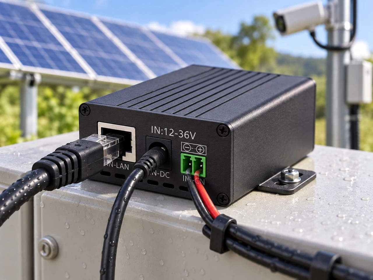
The Maxsol POE24V DC-to-PoE converter accepts 12–36V DC and provides an adjustable 12–57V PoE output, Gigabit Ethernet and an LCD voltage display. Its documented continuous load for 12V-to-48V conversion is no more than 30W. A maximum conversion efficiency of up to 94% is documented, but this is not a guaranteed design efficiency for every input voltage, output setting and load.
Accordingly, do not size a system by assuming that it will continuously achieve the maximum efficiency. Obtain or measure efficiency at the intended operating point, or enter a clearly identified engineering assumption and perform a sensitivity check.
Calculate cable loss without double-counting it
Resistive loss in a DC cable can be estimated from:
Ploss = I² × Rloop
Where:
Iis the current in amperesRloopis the total outgoing and return conductor resistance in ohms
Voltage drop is:
Vdrop = I × Rloop
PoE Ethernet cable losses depend on conductor resistance, current, cable length, connection quality and the pairs used for power. Long cable runs therefore affect both energy consumption and the voltage available at the powered device.
If input power has already been measured at the battery or source while the complete system is operating, converter and cable losses are normally included in that reading. Do not add them again.
Include auxiliary equipment explicitly
Small continuous loads can have a substantial daily effect. A 24-hour control, communications or monitoring load may consume more energy per day than a higher-power device that operates briefly.
List each auxiliary load separately, including:
- DC distribution equipment
- Routers and unmanaged switches
- Cabinet ventilation
- Temperature control
- Lighting
- Alarm interfaces
- Remote monitoring electronics
- Contactors and relays with continuously energised coils
Also check whether any controller or converter has a no-load or standby consumption. Use a documented value or a measurement rather than assuming it is negligible.
Convert power into daily energy demand
Solar and battery systems are sized in energy as well as power. Watts describe an instantaneous rate; watt-hours describe the energy consumed over time.
For a constant load:
Eday = P × 24
For loads with several operating states:
Eday = (P1 × t1) + (P2 × t2) + … + (Pn × tn)
Where the operating hours add up to the relevant daily schedule.
Illustrative source-side calculation
The following figures demonstrate the arithmetic only. They are not typical device values or a recommended UK design assumption.
Suppose source-side measurements produce this schedule:
| Operating state | Source-side power | Duration | Energy |
|---|---|---|---|
| PoE chain in daytime mode | 11W | 12h | 132Wh |
| PoE chain in night mode | 18W | 12h | 216Wh |
| Separate network equipment | 4W | 24h | 96Wh |
| Scheduled auxiliary load | 2W | 6h | 12Wh |
| Total | 456Wh/day |
Because the PoE chain was measured at its DC source, its figures already include the converter and cable losses present during the test. The calculated design demand for this illustrative schedule is 456Wh per day.
Real operating periods must come from the project’s design-month schedule. If night mode, heating or other weather-dependent functions vary, calculate more than one case and use the applicable worst credible energy case.
Do not replace the energy calculation with nameplate power
Multiplying a device’s maximum wattage by 24 hours can be useful as an upper-bound scenario, but it may oversize the system if the maximum occurs only briefly. Using a low observed average can create the opposite problem if the measurement missed winter or high-load conditions.
A sound design records:
- Measured normal power
- Measured or documented peak power
- Duration of each operating state
- Seasonal changes
- The measurement location
- Which losses are already included
Select autonomy and usable storage assumptions
Autonomy is the period for which the battery is expected to support the load without sufficient solar replenishment. It is a design requirement, not a fixed property of a solar kit.
For a daily demand of Eday and N autonomy days, the energy that must be delivered is:
Erequired = Eday × N
Nominal battery capacity must then account for the permitted usable portion of the battery and any delivery losses not already included:
Ebattery, nominal = Erequired ÷ (U × D)
Where:
Uis the approved usable storage fractionDis the applicable battery-to-load delivery factor not already captured by source-side measurements
Do not assign a universal usable percentage. Confirm the permitted depth of discharge, temperature limits, ageing basis and protection behaviour for the selected battery and controller.
Nominal watt-hours are not delivered watt-hours
A battery marked with a nominal watt-hour capacity does not promise that every nominal watt-hour will be delivered to the PoE device. Available energy can be affected by:
- Battery-management cut-off thresholds
- Permitted depth of discharge
- Battery temperature
- Current draw
- Converter cut-off voltage
- Wiring loss
- Battery age and design-life criteria
- Required reserve at the end of the autonomy period
This distinction is important when comparing packaged systems. The Maxsol CS8040 80W, 45Ah solar system documents an 80W monocrystalline panel, a 12.8V 45Ah 576Wh LiFePO4 battery, an MPPT controller and three 12V DC outputs. The 576Wh figure is nominal storage; it is not a universal statement of usable delivered energy or runtime.
The Maxsol CS12060 120W, 60Ah solar system documents a 120W monocrystalline panel, a 12.8V 60Ah 768Wh LiFePO4 battery, an MPPT controller and three 12V DC outputs. Its larger nominal panel and battery ratings do not remove the need to calculate load, losses, autonomy and winter solar input.
| Calculation reference | CS8040 | CS12060 |
|---|---|---|
| Panel nameplate rating | 80W | 120W |
| Nominal battery voltage | 12.8V | 12.8V |
| Nominal battery capacity | 45Ah | 60Ah |
| Nominal battery energy | 576Wh | 768Wh |
| Documented DC outputs | Three 12V outputs | Three 12V outputs |
| Charge controller | MPPT | MPPT |
These products are useful calculation reference points, not evidence of runtime or tested compatibility with a particular PoE device.
For a broader treatment of reserve duration, battery capacity and system architecture, see the guide to sizing an off-grid solar power system for CCTV.
Estimate design-month solar input
The solar array should be evaluated for the selected design month, not against an annual-average solar figure. For UK outdoor systems, winter operation often requires particular attention because solar input, daylight-dependent load behaviour and weather-related auxiliary consumption can all change together.
Obtain design-month peak sun hours or equivalent irradiation data for the actual site and panel orientation. Do not substitute an unverified national figure.
A basic array calculation is:
Parray = Esolar,target ÷ (Hdesign × Ksolar)
Where:
Esolar,targetis the daily energy that the array must provideHdesignis the site-specific design-month peak sun hoursKsolaris the verified or explicitly assumed overall solar-path factorParrayis the required panel nameplate power
The solar-path factor may need to cover controller conversion, battery charging, wiring, temperature, orientation, contamination and other applicable effects. Its components should be documented so they can be reviewed independently.
Decide whether the array must only sustain the load or also restore reserve
An array sized merely to replace one day’s normal consumption may maintain operation under design conditions, but it may restore depleted battery reserve very slowly.
If reserve energy must be replenished within R suitable charging days, a simplified target is:
Esolar,target = Eday + (Ereserve ÷ R)
The array calculation then becomes:
Parray = [Eday + (Ereserve ÷ R)] ÷ (Hdesign × Ksolar)
Define what constitutes a suitable charging day and whether the system is expected to carry the full load while restoring reserve. Recovery requirements can materially increase the panel rating.
Check several design cases
At minimum, compare:
- Normal design-month operation: expected load and expected solar input.
- High-load operation: night functions, heating, heavy traffic or other maximum-duty states.
- Autonomy event: insufficient solar contribution for the selected period.
- Recovery: simultaneous load operation and battery recharge.
- Low-temperature case: where the battery or electronics have relevant temperature constraints.
Panel nameplate watts should not be treated as continuous output. A nominal 120W panel does not supply 120W throughout the day, and multiplying its rating by daylight hours is not a valid energy estimate.
Verify voltage, protocol and commissioning measurements
Energy capacity does not establish PoE compatibility. A solar system may have enough watt-hours but still be unable to power the device because of voltage, polarity, pinout, protocol or peak-current differences.
Before connecting equipment, verify:
- DC input-voltage range of the converter or injector
- PoE output voltage required by the powered device
- Output polarity and Ethernet pinout
- Passive PoE versus IEEE-compatible PoE requirements
- Whether powered-device detection or negotiation is required
- Continuous and peak power limits
- Cable category, conductor resistance and length
- Voltage at the powered device under maximum load
- Low-voltage cut-off and restart behaviour
- Earthing, surge protection and environmental enclosure requirements
The documented facts for the POE24V converter do not establish IEEE powered-device detection or negotiation. Its adjustable voltage range must not be interpreted as automatic protocol compatibility. Confirm voltage, polarity, pinout and protocol before use.
Similarly, the linked Maxsol solar systems and converter are calculation examples rather than a tested compatible bundle.
Commission the finished system at the measurement boundary
Once installed, compare actual measurements with the design worksheet. Commissioning should include:
- Battery-bus voltage with no load and under maximum load
- Source current in each operating state
- Converter input and output voltage
- Voltage at the far end of the Ethernet cable
- Night-mode or maximum-feature operation
- Start-up after low-voltage shutdown
- Daily watt-hour consumption over a representative period
- Solar charging current under recorded weather conditions
- Controller status and protection events
Where possible, log energy rather than relying on a single current reading. Wireless traffic, IR illumination, heaters and other functions may cycle during the day.
If measured daily demand is higher than calculated, identify the difference rather than masking it with an arbitrary margin. Possible causes include an omitted load, longer duty cycle, lower conversion efficiency, excessive cable resistance or a measurement taken at a different point in the power chain.
Common sizing mistakes to avoid
- Sizing from the PoE class alone: A PoE class or maximum rating is not a daily energy measurement.
- Ignoring the upstream network load: Routers, switches and radios may run continuously.
- Using nominal battery Wh as usable energy: Controller limits and operating conditions reduce delivered capacity.
- Applying annual-average solar data: The design month may have a very different energy balance.
- Assuming maximum converter efficiency: “Up to” efficiency is not guaranteed at every operating point.
- Adding losses twice: Source-side measurements may already include conversion and cable losses.
- Ignoring voltage drop: Adequate total energy does not ensure sufficient voltage at the device.
- Confusing watts with watt-hours: Converter capacity is checked in watts; daily consumption is calculated in watt-hours.
- Skipping recovery sizing: A system may run normally yet fail to restore reserve within the required period.
- Treating adjustable-voltage output as PoE negotiation: Electrical and protocol compatibility must be verified separately.
A practical calculation checklist
Before selecting equipment, complete these fields:
- Measured power for every load and operating state
- Hours per day in each state during the design month
- Converter efficiency at the intended input, output and load
- DC and Ethernet cable resistance or measured loss
- Total daily source energy in watt-hours
- Required autonomy in days
- Approved usable-battery and temperature assumptions
- Site-specific design-month solar input
- Documented solar-path losses
- Required reserve-recovery period
- Continuous and peak converter requirements
- PoE voltage, polarity, pinout and protocol
- Environmental, protection and enclosure requirements
- Commissioning measurements and pass criteria
The resulting design must pass three independent checks: sufficient instantaneous power, sufficient stored and generated energy, and correct electrical and PoE compatibility.
As a next step, compare the linked Maxsol solar-system and converter examples with the project’s port count, measured load, cable distance, power range, environment and management requirements. Use the calculations above to determine whether their documented ratings suit the design rather than selecting solely by panel watts or nominal battery capacity.