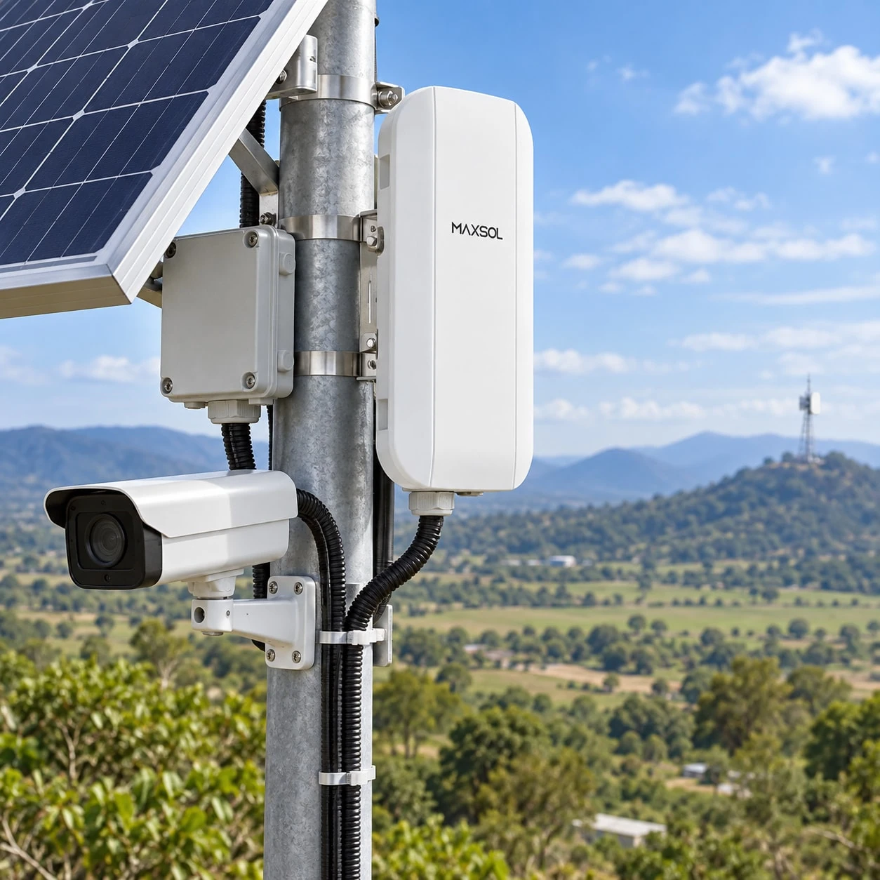
Solar Power for CCTV Deployment Checklist: UK Guide
Use this practical pre-deployment checklist to verify CCTV loads, solar access, autonomy, interfaces, monitoring and commissioning evidence before buying.
By Maxsol Team

A reliable solar CCTV project starts with evidence, not a nominal camera wattage or panel rating. Before procurement, document every day and night load, confirm the power and data interfaces, survey winter solar access, set autonomy and recovery objectives, and agree how the system will be monitored and maintained.
This solar power for CCTV deployment checklist helps project teams identify missing information before equipment reaches site. It is a pre-deployment review rather than a substitute for electrical design, structural assessment or site-specific energy modelling.
| Review area | Evidence required before procurement |
|---|---|
| Electrical load | Measured or documented average, maximum and start-up demand for every device |
| Solar access | Design-month shading survey, orientation options and horizon obstructions |
| Interfaces | Voltage range, polarity, PoE method, pinout, connector and Ethernet requirements |
| Recording | Recorder location, storage period, codec assumptions and event behaviour |
| Backhaul | Link path, expected traffic, power draw, mounting height and fallback arrangements |
| Autonomy | Required operating time without useful solar input and acceptable recovery time |
| Environment | Temperature, water, dust, condensation, corrosion and wind exposure |
| Operations | Monitoring points, alarm thresholds, maintenance access and isolation method |
| Commissioning | Recorded energy, voltage, current and network performance under realistic conditions |
Document cameras, recording and backhaul loads
Build a complete load schedule before choosing the panel, battery, controller or enclosure. The schedule must cover everything powered by the off-grid system, not only the cameras.
For each device, record:
- manufacturer and model;
- quantity;
- input voltage and acceptable voltage range;
- average operating power;
- highest continuous power;
- start-up or inrush demand where applicable;
- daytime and night-time operating profile;
- seasonal functions such as heaters or demisters;
- conversion losses between the battery and load;
- required operating hours;
- criticality if energy becomes limited.
Separate daytime and night-time demand
A camera may draw more power at night when infrared illumination activates. PTZ movement, white-light deterrents, heaters, microphones and edge analytics can also create variable or coincident loads. Do not assume that the value observed in daylight represents the overnight load.
Create at least three operating cases:
- Normal daytime: cameras running without night illumination.
- Normal night-time: all expected infrared, lighting and environmental functions active.
- Maximum credible demand: simultaneous PTZ movement, radio traffic, recording activity, heaters or auxiliary equipment.
Measure real devices where practical. If relying on datasheets, record whether a figure is typical, maximum or limited to a particular operating mode. Procurement decisions should use defensible maximum and duty-cycle assumptions, not an undocumented “typical CCTV load”.
Include recording architecture
Clarify where video will be recorded:
- locally on a memory card;
- on a recorder inside the solar enclosure;
- at a remote control room;
- in a hosted platform;
- through a combination of local and remote recording.
A local recorder adds a continuous load and may need temperature management. Remote recording transfers more traffic over the backhaul and may increase radio or router activity. Event-only transmission can reduce average traffic, but it must be tested against the required evidence quality and recording policy.
Document the proposed resolution, frame rate, codec, bitrate mode, number of streams and retention requirement. These settings influence both storage and network demand.
Account for every network device
The load schedule may need to include:
- PoE switches or injectors;
- DC converters;
- wireless bridges;
- mobile routers;
- Ethernet extenders;
- fibre media converters;
- environmental sensors;
- enclosure fans or heaters;
- charge-controller communications;
- remote restart relays.
For example, the Maxsol CPE295 5.8GHz wireless CPE documents 6.5W full-load consumption, a 2x2 14dBi directional MIMO antenna, one Gigabit LAN port and support for IEEE 802.3af/at or 9–48V DC power. Those details can inform a load and interface schedule, but they do not establish actual link throughput at a particular site. Path clearance, interference, alignment and configuration still need to be assessed.
If the project architecture is not yet settled, review the practical stages involved in building a solar-powered CCTV system for remote areas before freezing the bill of materials.
Survey shade, mounting and environmental exposure
A panel position that appears clear during a summer visit may perform poorly in the winter design month. UK projects must account for shorter winter days, lower sun angles, extended cloud and shadows cast by nearby objects.
The solar survey should record:
- usable mounting area;
- proposed panel orientation and inclination;
- obstructions across the solar path;
- shading from trees, hedges, buildings, poles and terrain;
- potential future vegetation growth;
- self-shading from cameras, antennas or enclosure hardware;
- access for cleaning and inspection;
- cable route and approximate cable length;
- exposure to wind, spray, road dirt, birds and vandalism.
Take date-stamped photographs from the proposed panel position, including the full relevant horizon. Where the project is sensitive to winter continuity, use a proper solar-path or shading assessment rather than a visual judgement alone.
Assess the structure, not just the sunlight
Confirm that the pole, wall, column or ground mount can accommodate the proposed panel area, enclosure and antennas. The assessment should consider wind loading, fixings, corrosion environment, cable strain relief and the effect of adding equipment at height.
Avoid allowing solar modules, radio antennas and cameras to compete for the same small mounting area. Radio alignment may dictate one direction while the best solar orientation requires another. A modular mounting arrangement can reduce these conflicts.
Define enclosure conditions
The enclosure is part of the power system. Record the expected:
- ambient temperature range;
- direct solar heating;
- rain and wind-driven water exposure;
- dust, insects and airborne contamination;
- condensation risk;
- salt or corrosive exposure;
- likelihood of flooding or standing water;
- tampering and impact risk.
Ingress protection alone does not resolve condensation or internal heat. Check cable-gland selection, drainage, ventilation strategy, component spacing and whether heat-generating equipment is installed beside the battery or charge controller.
The battery chemistry and controller must be assessed against expected charging and operating temperatures. Confirm the applicable manufacturer limits rather than assuming all LiFePO4 systems behave identically in cold conditions.
Confirm voltage, PoE and data interfaces
“PoE camera” does not by itself prove compatibility. Before ordering, confirm the voltage, negotiation method, polarity, pin assignment, connector type, power budget and Ethernet speed at every interface.
Use an interface schedule such as this:
| Connection | Questions to answer |
|---|---|
| Panel to controller | Are voltage, current, connectors and polarity within the controller limits? |
| Controller to battery | Are battery chemistry, nominal voltage and charging profile compatible? |
| Battery to DC load | Is the load’s full input range suitable across battery charge and discharge states? |
| DC converter to camera | Is the output regulated, and are voltage, polarity and pinout correct? |
| PoE source to device | Is it standards-based negotiated PoE or passive power? Which pairs and voltage are used? |
| Camera to network | Is the required Ethernet speed supported throughout the path? |
| Radio to network | Are port speed, VLAN, addressing and management requirements supported? |
Do not treat passive power as negotiated PoE
Some outdoor equipment accepts DC power over Ethernet conductors without IEEE negotiation. Other devices expect IEEE 802.3af, 802.3at or another defined method. Connecting equipment on voltage alone can result in failure or damage if polarity, pinout or protocol differ.
The Maxsol POE24V DC-to-PoE converter accepts 12–36V DC and provides adjustable 12–57V PoE output, Gigabit Ethernet and an LCD voltage display. Its documented continuous load when converting 12V to 48V is no more than 30W. These facts do not establish IEEE PoE negotiation, so installers must verify the powered device’s voltage, polarity, pinout, protocol and maximum demand.
Also check the load at the end of the real cable run. Voltage drop depends on conductor material, cable size, length, current and connector condition. A converter that appears suitable on the bench may not maintain the required input at the camera after cable losses and cold-weather battery voltage changes.
Check the complete data path
Power compatibility does not guarantee a functioning video path. Record:
- camera Ethernet speed;
- switch and converter port speeds;
- duplex and auto-negotiation behaviour;
- VLAN and addressing plan;
- multicast or discovery requirements;
- management access method;
- time synchronisation source;
- cybersecurity configuration responsibility;
- expected aggregate and peak bitrate.
For wireless backhaul, conduct a path assessment and spectrum survey where appropriate. Confirm line of sight, Fresnel-zone clearance, mounting stability, channel options and interference conditions. Product range labels are not a guarantee of usable CCTV throughput, latency or availability.
Set autonomy, recovery and load-priority objectives
Autonomy is the period the CCTV system is expected to operate without useful solar generation. It should be a stated project objective, not an accidental result of the selected battery size.
Agree the following before sizing:
- target autonomy under the defined load;
- design month and weather assumptions;
- permitted battery depth of discharge;
- minimum state of charge;
- acceptable loss of optional services;
- required recovery time after a low-energy event;
- whether another charging source is available;
- consequences of complete shutdown.
A larger battery may extend autonomy, but it also requires enough generation to recover after discharge while continuing to supply the active load. Increasing storage without checking recharge capability can produce a system that survives a poor period but remains undercharged afterwards.
For the calculation process, use a dedicated off-grid solar sizing guide for CCTV. Keep the resulting assumptions with the project records so another engineer can review the load, losses, solar input and reserve margins.
Define load priorities
Not every load needs the same protection. Assign each item to an agreed priority level.
| Priority | Typical objective | Possible response to low energy |
|---|---|---|
| Critical | Preserve core surveillance evidence | Keep selected cameras and essential networking active |
| Operational | Maintain normal system visibility | Reduce frame rate or disable non-essential streams if supported |
| Optional | Provide supplementary functions | Shed lighting, secondary radios or convenience loads |
| Recovery | Restore remote access safely | Reserve energy for controlled restart and monitoring |
Any automatic load shedding must be supported by the equipment and approved by the security designer. It should not silently undermine the recording or evidential requirement.
Use products as architecture references, not runtime promises
The Maxsol CS12060 solar power system documents a 120W monocrystalline panel, 12.8V 60Ah 768Wh LiFePO4 battery, MPPT controller and three DC12V outputs. These specifications provide inputs for a design review; they do not establish universal CCTV runtime.
Runtime depends on the full load, conversion losses, usable battery limits, temperature, solar access and recovery conditions. The linked solar system, converter and wireless CPE are architecture examples and should not be assumed to form a tested compatible bundle.
Plan monitoring, maintenance and physical access
A remote solar CCTV installation needs enough monitoring to distinguish an energy problem from a network, camera or recording fault.
Where supported by the selected equipment, consider collecting:
- battery voltage and state-of-charge indication;
- charge and load current;
- controller status and fault codes;
- low-voltage events;
- camera reachability;
- radio signal and link status;
- packet loss and latency;
- recording health;
- enclosure temperature;
- time of the last successful communication.
Define who receives alarms, what thresholds apply and what action is expected. A warning that is never reviewed has little operational value. Avoid relying on battery voltage alone as a precise state-of-charge measure unless the battery and monitoring method support that interpretation.
Design for safe maintenance
Confirm how an engineer will reach and work on:
- the solar panel;
- battery;
- controller;
- fuses and isolators;
- converters and switches;
- camera connectors;
- radio alignment controls;
- diagnostic ports.
Allow space to use test instruments without dismantling the entire enclosure. Labels should identify circuits, polarity, fuse ratings, isolation points and cable destinations. Keep an approved wiring diagram inside the project record rather than relying on installer memory.
The access plan should also address working at height, traffic or public-space constraints, landowner permission, locked gates and the availability of safe parking or lifting equipment. These are practical design inputs because difficult access increases the cost and duration of routine inspection.
Prepare a maintenance schedule covering:
- panel cleanliness and shading changes;
- loose or corroded fixings;
- damaged cables and glands;
- water or condensation inside enclosures;
- battery and controller status;
- antenna alignment;
- camera image quality;
- recording retrieval;
- alarm and remote-restart functions.
Commission with measured energy and network evidence
Commissioning should demonstrate that the installed system matches the approved design. A photograph showing that the camera is online is not enough.
Record the final equipment models, serial references where required, cable routes, settings and firmware versions. Then collect measurements under representative operating states.
Energy commissioning checks
Measure or verify:
- panel open-circuit and operating values using appropriate procedures;
- battery voltage and condition before load testing;
- controller charging state;
- current drawn by each major load;
- complete daytime system demand;
- complete night-mode demand;
- voltage at the source and at the remote device;
- converter input and output;
- response to maximum expected simultaneous load;
- low-voltage protection and restoration behaviour where safe to test.
Night functions should be activated deliberately rather than left untested until after handover. Confirm infrared illumination, PTZ movement, heaters, radios and auxiliary lighting as applicable.
Do not infer long-term solar performance from a short commissioning visit. Initial measurements confirm wiring and operating demand; ongoing monitoring is needed to compare real energy behaviour with the design assumptions.
Network and recording checks
The handover evidence should also include:
- camera connectivity and management access;
- measured throughput across the backhaul;
- latency, packet loss and link stability during testing;
- video quality at the intended resolution and frame rate;
- simultaneous stream performance;
- successful local or remote recording;
- playback and export of a test event;
- correct timestamps and time synchronisation;
- recovery after a controlled power interruption;
- alert delivery and escalation;
- remote restart or isolation operation, if provided.
Wireless testing should be performed with the final antenna positions, channel plan and mounting hardware. A bench test cannot reproduce path obstruction, local interference or pole movement.
Set acceptance criteria before testing
Commissioning is easier when pass or fail thresholds are agreed in advance. Specify acceptable voltage ranges, maximum load, recording behaviour, link performance, alarm response and recovery sequence in the design documentation.
Any deviation should be recorded with one of three outcomes:
- corrected and retested;
- accepted through a documented design change;
- left open with an owner and completion date.
The final handover pack should include the load schedule, solar survey, wiring diagram, interface register, configuration backup, commissioning results, maintenance instructions and photographs of the completed installation.
Common pre-deployment reasons to pause procurement
Do not freeze the equipment list if any of these questions remain unanswered:
- Is the night-time camera load still based on a daytime estimate?
- Are radio, router, converter and enclosure loads missing?
- Has winter shading been assessed at the actual panel position?
- Is the PoE method described only as “48V” without protocol or pinout?
- Is autonomy stated without a design load and battery operating limits?
- Has battery recharge after a low-energy period been considered?
- Is wireless performance based only on a range label?
- Is there no agreed response when stored energy becomes limited?
- Can maintenance staff safely reach the panel and enclosure?
- Are commissioning acceptance limits absent?
Resolving these gaps before purchasing equipment is usually easier than redesigning the power, mounting or backhaul arrangement on site.
Final pre-deployment decision
Proceed only when the project team can trace each selected component to a documented load, interface, environmental condition and operational objective. Retain those assumptions so commissioning measurements can be compared with the original design.
As a practical next step, compare the linked Maxsol solar system, DC-to-PoE converter and wireless CPE against your required port count, measured load, cable and radio distance, voltage architecture, environmental exposure and management requirements. Treat each as a separate architecture option until compatibility has been verified across the complete CCTV system.