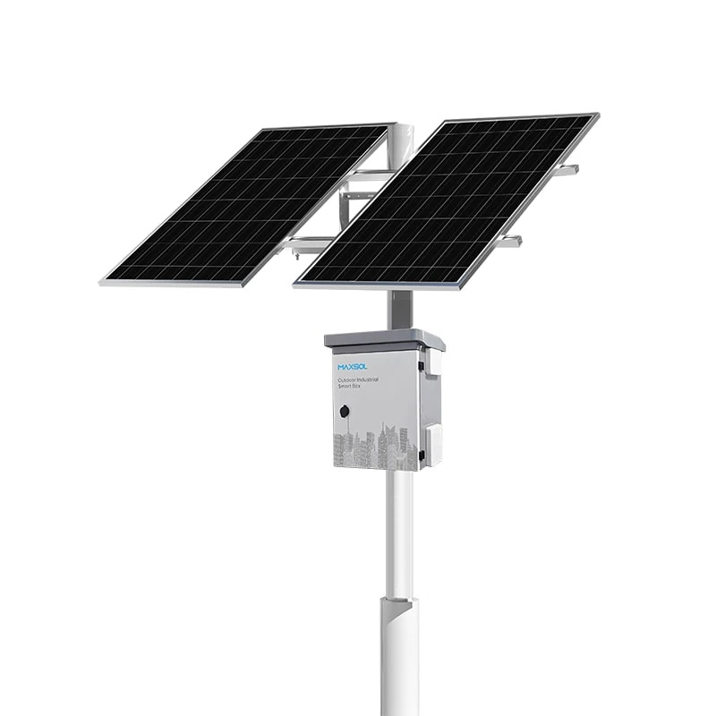
Solar Security Cameras for Farms, Car Parks and Remote Sites
Compare solar security camera designs for UK farms, car parks and remote facilities, covering power, connectivity, mounting and maintenance.
By Maxsol Team

Solar-powered security cameras can suit farms, car parks and remote facilities where installing a mains supply or fixed data cable would be costly or disruptive. However, these locations place very different demands on coverage, solar exposure, mounting, wireless connectivity, battery autonomy and maintenance access.
The right design starts with the camera load and operating conditions—not the panel wattage printed on a product page. Farms often need long links and protection from vegetation or machinery; car parks need reliable identification views and carefully positioned equipment; remote facilities usually prioritise autonomy, fault reporting and minimal service visits.
Farm boundaries and agricultural buildings
Agricultural sites rarely resemble a neat, open installation plan. A farm may combine exposed field boundaries, shaded yards, metal-clad buildings, gateways, livestock areas and isolated sheds, each presenting a different design problem.
Coverage is usually divided between two tasks:
- Monitoring movement across wide boundaries, tracks or fields
- Capturing useful detail at controlled points such as gates, doors and fuel stores
Wide-area observation and identification should not be treated as the same requirement. A single camera placed high on a building may provide a broad overview but insufficient detail at a distant entrance. Conversely, a camera aimed tightly at a gateway may leave nearby routes unobserved.
Account for seasonal shade and site activity
Trees, hedges and buildings can affect solar exposure, while growing vegetation may gradually obstruct both the panel and the camera view. Installers should assess the proposed position at different times of day and consider how lower seasonal sun angles could change shading. Avoid assuming that a bright survey day represents year-round conditions.
Mounting also requires practical coordination with farm operations. A post that appears convenient may obstruct machinery, be vulnerable to livestock, or sit within an area regularly accessed for hedge cutting. Cable routes and enclosures should be kept away from impact, abrasion and unauthorised access.
Agricultural buildings introduce another complication: metal roofs and walls can weaken or reflect wireless signals. Before selecting a wireless route, record the actual path between the camera position and receiving point, including trees, silos, barns and moving machinery.
Where a point-to-point connection is being considered, the Maxsol CPE295 5.8GHz directional wireless CPE is one possible networking component. Its documented features include 5.8GHz operation, a 2×2 14dBi directional MIMO antenna, one Gigabit LAN port, IEEE 802.3af/at or 9–48V DC power support, and 6.5W full-load consumption. Distance labels do not guarantee a working farm link or its throughput: installers must verify line of sight, interference, alignment and applicable local radio requirements.
Car park entrances and open parking areas
Car parks may offer clearer solar exposure than agricultural sites, but their surveillance requirements are often more demanding. Cameras can be expected to cover entrances, pedestrian routes, payment areas, parked vehicles and boundary approaches, with each view requiring a different angle and level of detail.
The entrance is normally the most constrained location. If the operational requirement includes capturing vehicle characteristics or number plates, the designer must determine lane width, vehicle position, direction of travel, speed, lighting and camera angle. Solar power does not compensate for an unsuitable imaging design.
Open parking areas also produce difficult contrasts between headlamps, shade, reflective surfaces and changing daylight. Camera imaging features must therefore be specified separately. Maxsol’s linked solar and wireless products provide power or network connectivity; they do not provide camera imaging functions.
Position solar equipment without creating new risks
Panel and cabinet placement should consider:
- Vehicle strike risk and protection from reversing vehicles
- Tampering and unauthorised access
- Shadows from lighting columns, signs, trees and nearby structures
- Safe maintenance access without closing a traffic lane unnecessarily
- Cable protection between the panel, power enclosure, camera and network device
- Wind loading and the suitability of the supporting column or structure
Existing lighting columns may appear to be convenient mounting points, but their structural capacity, ownership, internal space and electrical arrangements must be confirmed. Never assume that permission to fit a camera also permits a solar panel or additional cabinet on the same column.
Car parks surrounded by buildings may have suitable network access nearby. In that situation, a short wired connection, managed wireless link or cellular connection might be more practical than a long-distance bridge. The choice should follow an RF and network survey rather than a preference for a particular transmission method.
Remote facilities with limited service access
At remote compounds, utility sites, storage areas and unattended equipment locations, the main design priority is often resilience between planned visits. A system that operates during favourable weather but requires repeated manual resets is unlikely to meet the operational need.
Service access changes the value of every design decision. If reaching the site requires a long journey, an escort, specialist access equipment or a restricted maintenance window, designers should prioritise:
- Sufficient energy margin for expected low-generation periods
- Remote visibility of camera, network and power status
- Equipment that can be isolated and tested safely
- Accessible protective devices and labelled terminations
- Straightforward replacement of field-serviceable components
- Event and fault reporting that distinguishes power, network and camera issues
Remote facilities may also have a relatively small surveillance load but a demanding autonomy target. A single camera and radio running continuously can consume more energy over several poor-generation days than their modest wattage suggests.
For larger measured loads or longer design autonomy, the Maxsol CS400150 400W and 1920Wh solar power system is a selection example. Its documented configuration comprises two 200W panels, a 12.8V 150Ah 1920Wh LiFePO4 battery, MPPT control and four DC12V outputs. These nominal ratings do not establish usable delivered energy, guaranteed runtime or suitability for a particular remote site.
Compare power, connectivity and mounting needs
The following matrix highlights the different priorities. It describes hypothetical design scenarios, not customer installations or measured product performance.
| Design factor | Farm boundary or building | Car park entrance or open area | Remote facility |
|---|---|---|---|
| Coverage priority | Broad boundary awareness plus detailed views at gates and buildings | Defined vehicle and pedestrian views, often with higher detail at entrances | Focused monitoring of access points, assets or equipment |
| Shade risk | Trees, hedges, barns, silos and seasonal vegetation | Buildings, signs, lighting columns, trees and parked vehicles | Terrain, structures, vegetation or an apparently open site with seasonal shadow |
| Typical mounting concern | Machinery, livestock, corrosion, vegetation maintenance and uneven ground | Vehicle impact, tampering, safe working near traffic and column suitability | Wind exposure, difficult access, tamper resistance and service safety |
| Connectivity options | Directional wireless links, local building networks or cellular service | Nearby wired network, managed wireless link or cellular service | Long-range directional link or cellular service, subject to survey |
| Autonomy emphasis | Allowance for seasonal demand, shading and temporary obstructions | Continuity through poor weather without oversized or unsafe street furniture | Greater margin where service visits are difficult or slow |
| Service access | Often available, but may conflict with farm operations | Usually accessible, although traffic control or lifting equipment may be needed | Infrequent, costly or restricted; remote diagnostics become more important |
| Common design mistake | Treating the whole farm as one unobstructed radio and solar environment | Using a wide overview camera where entrance detail is required | Selecting equipment by nominal battery capacity without accounting for total losses |
The table should be used to identify priorities, not to select panel and battery sizes directly. Detailed power sizing requires measured or verified loads, operating schedules, conversion losses and a defined autonomy objective. A separate guide explains how to size an off-grid solar power system for CCTV once those inputs are available.
Select components by measured requirements
Start by producing a requirements handover that separates surveillance performance from power and communications. This prevents an installer from being given only a location plan and an ambiguous request for “a solar camera”.
1. Define the surveillance outcome
For every camera position, record:
- The area or access point to be observed
- Whether the objective is detection, observation, recognition or identification
- Required recording hours and event behaviour
- Night-time lighting conditions
- Camera heater, illuminator, motor or other variable loads
- Recording destination and response to loss of connectivity
Obtain maximum and typical power consumption from the camera supplier. If features switch on at night or in cold conditions, use the relevant worst-case value rather than a low daytime figure.
2. Create a complete power budget
Include every continuously or intermittently powered device:
- Camera
- Infrared or white-light illuminator
- Wireless bridge or cellular router
- PoE converter, injector or switch
- Controller, monitoring and communication equipment
- Enclosure heating, cooling or ventilation where required
- Conversion and cable losses
As a hypothetical calculation only, a combined 18W continuous load would consume 432Wh over 24 hours before accounting for conversion, cabling, controller overhead or temperature effects. That figure is a design assumption, not measured performance of a Maxsol system.
A nominal 768Wh battery therefore cannot be treated as providing 768Wh to the connected devices. Usable delivered energy depends on the supplied configuration, battery operating limits, controller behaviour, conversion losses, load voltage, temperature and protection settings. There is no universal runtime calculation that applies to every installation.
For a smaller verified load, the Maxsol CS12060 120W and 768Wh solar power system can be assessed as one power option. Its documented components include a 120W monocrystalline panel, 12.8V 60Ah 768Wh LiFePO4 battery, MPPT controller and three DC12V outputs; RS485 is optional. These specifications do not confirm autonomy or compatibility with a chosen camera.
For both CS12060 and CS400150, check the current datasheet and supplied configuration. In particular, confirm controller limits for PV voltage, current and power, as well as battery charging temperatures, protection behaviour and output arrangements.
3. Survey the connectivity path
A network handover should document:
- Camera bitrate assumptions and peak traffic
- Recording and live-view destinations
- Required uplink and downlink capacity
- Latency or availability requirements
- IP addressing, VLAN and cybersecurity requirements
- Line of sight and Fresnel-zone obstructions for directional links
- Local interference at the intended frequency
- Mounting height, alignment and cable length
- Response when the link is lost
Product wireless-rate or distance labels are not application throughput guarantees. A link can associate successfully yet still be unsuitable for stable video transmission because of interference, poor alignment, obstruction or competing traffic.
4. Match the enclosure to the actual threat
Outdoor suitability involves more than weather protection. An enclosure may need resistance to rain, wind-driven debris, dust, impact, corrosion, condensation and unauthorised access. These requirements should be stated separately rather than reduced to a single outdoor rating.
The distinction between ingress and impact protection is explained in this guide to IP65 and IK10 outdoor CCTV enclosure requirements. Confirm the ratings and construction of the specific supplied enclosure rather than assuming that every part of an assembled system has the same protection level.
Requirements handover checklist
Before procurement, the designer should issue a handover containing:
- Marked-up camera locations and required fields of view
- Maximum, typical and time-dependent loads for every device
- Required autonomy and acceptable degraded operating modes
- Solar exposure and shading survey for each panel position
- Radio survey or evidence supporting the selected connection
- Mounting details, structural responsibility and cable routes
- Environmental, impact and access-control requirements
- Network addressing, recording and remote-management plan
- Acceptance criteria and test responsibilities
- Current datasheets and configuration records for all proposed components
Linked products should be treated as individual selection examples, not as a tested compatible bundle. Voltage, connector, polarity, startup demand, PoE method and controller behaviour must all be checked before connection.
Plan maintenance and acceptance checks
Commissioning should prove that the installed system meets the written requirement, not merely that a live image appears on a laptop. Record baseline values so future technicians can identify deterioration or misalignment.
Acceptance checks should include:
- Confirmation of each required view by day and under representative low-light conditions
- Verification of recording, event transmission and time synchronisation
- Measured device voltage and current under relevant operating modes
- Confirmation that high-load features start correctly
- Inspection of panel orientation and current shading
- Wireless signal, stability and throughput checks under expected traffic
- Test of restart behaviour after simulated power and network interruption
- Inspection of cable glands, drip loops, strain relief and earthing arrangements
- Confirmation that cabinets, fixings and access points are secure
- Verification of remote alarms, status reporting and maintenance access
The maintenance plan should reflect the scenario. Farm systems may need inspections after vegetation growth or changes to buildings. Car park systems may require checks following column damage, layout changes or new signage. Remote facilities benefit from condition-based monitoring backed by planned visits before predictable periods of difficult access.
Keep an installation record with equipment settings, wiring diagrams, alignment information, photographs and measured commissioning values. When requirements change—such as adding a camera, enabling an illuminator or increasing recording traffic—repeat the power and network assessment rather than assuming spare capacity.
As a practical next step, compare the linked Maxsol power and wireless models with the project’s verified port count, total load, link distance, autonomy, environment and management requirements. Confirm current datasheets and the supplied configuration before treating any component as compatible with the complete camera system.